
A 3 phase pad mounted transformer is a critical component in modern electrical distribution networks, particularly in commercial, industrial, and utility applications. Installed at ground level within secure enclosures, these transformers step down medium voltage power to usable levels for facilities and equipment.
Their reliability directly affects uptime, safety, and operational continuity. Preventing equipment failure in and around these transformers is essential because faults can disrupt entire operations, damage connected machinery, and lead to costly downtime.
Understanding how these transformers function, what risks they face, and how to maintain them properly helps organizations safeguard infrastructure and ensure consistent power delivery.
Understanding 3-Phase Pad Mounted Transformers
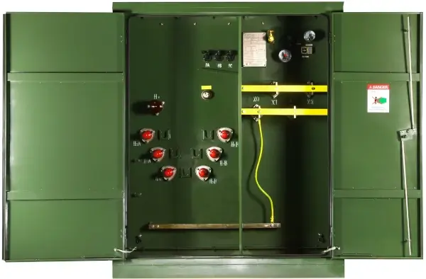
A 3 phase pad mounted transformer is an outdoor, tamper resistant, ground mounted unit used in underground power distribution systems. It converts higher primary voltage from utility lines to lower secondary voltage suitable for buildings, equipment, or localized distribution networks.
These transformers are commonly used in:
- Industrial facilities with heavy machinery loads
- Commercial complexes and campuses
- Renewable energy installations
- Utility distribution grids in urban areas
Because they are enclosed and weather resistant, they reduce exposure risks compared to pole mounted transformers. However, their ground level placement and constant load exposure introduce unique failure risks that require proactive prevention strategies.
Common Causes of Equipment Failure in Pad Mounted Transformers
Preventing failure begins with understanding what typically goes wrong. Several electrical, thermal, environmental, and operational factors contribute to transformer issues.
Thermal Overload and Insulation Breakdown
Transformers generate heat during operation. Excessive load, poor ventilation, or aging insulation can cause internal temperatures to rise beyond design limits. Over time, heat degrades insulation, leading to winding faults and eventual transformer failure.
Signs of thermal stress include:
- Discolored or degraded insulating oil
- Elevated operating temperature readings
- Repeated tripping under normal load
- Reduced insulation resistance
Moisture Ingress and Contamination
Although sealed, pad mounted transformers are exposed to environmental moisture, flooding, and soil humidity. Water ingress contaminates insulating oil and reduces dielectric strength. This increases the risk of internal arcing and catastrophic breakdown.
Moisture contamination often occurs due to:
- Damaged gaskets or seals
- Corrosion at enclosure joints
- Aging bushings
- Flood prone installation sites
Electrical Faults and Short Circuits
External faults such as cable failures, lightning surges, or downstream short circuits place extreme stress on transformer windings. High fault currents can deform windings or damage insulation instantly.
Typical electrical stress sources include:
- Switching surges
- Faulty underground cables
- Load imbalance across phases
- Harmonic distortion from nonlinear loads
Mechanical Damage and Vibration
Ground mounted transformers may experience mechanical stresses from nearby construction, vehicle impact, or soil settlement. Internal winding displacement or core misalignment can occur without obvious external signs, gradually leading to failure.
Importance of Proper Transformer Sizing and Load Management
One of the most overlooked causes of premature transformer failure is improper sizing. When a transformer operates continuously near or above rated capacity, thermal aging accelerates dramatically.
Correct sizing considers:
- Peak demand and future load growth
- Load diversity across phases
- Harmonic producing equipment
- Ambient temperature conditions
Load imbalance is particularly harmful in three phase systems. Unequal phase loading causes uneven heating and localized insulation stress. Maintaining balanced loads extends transformer life and improves efficiency. To explore three phase pad mount transformers visit here.
Preventive Maintenance Strategies
Routine maintenance is the most effective method for preventing equipment failure. A structured program identifies early warning signs before they become critical faults.
Oil Testing and Condition Monitoring
Transformer oil acts as both insulation and cooling medium. Its condition reflects internal health. Regular laboratory analysis can detect moisture, dissolved gases, and insulation degradation long before failure occurs.
Key oil tests include:
- Dissolved gas analysis
- Moisture content measurement
- Dielectric strength testing
- Acidity and oxidation levels
Infrared Thermography Inspections
Thermal imaging identifies abnormal heating patterns without shutting down equipment. Hot spots may indicate loose connections, internal faults, or overload conditions.
Thermography can reveal:
- Bushing heating
- Cable termination issues
- Uneven phase loading
- Cooling inefficiencies
Electrical Testing and Diagnostics
Periodic electrical testing verifies insulation integrity and winding condition. Trending results over time allows predictive maintenance planning.
Common diagnostic tests:
- Insulation resistance testing
- Power factor testing
- Turns ratio verification
- Winding resistance measurement
Environmental Protection Measures
Environmental exposure significantly influences transformer lifespan. Proper site design and protective measures reduce contamination, corrosion, and physical damage risks.
Effective protection approaches include:
- Elevated concrete pads in flood prone areas
- Protective bollards against vehicle impact
- Drainage control around installation site
- Corrosion resistant coatings and sealed joints
Maintaining clearances around the transformer also improves airflow and reduces overheating risk from surrounding debris or vegetation.
Monitoring and Smart Transformer Technologies
Modern monitoring systems enable continuous condition tracking rather than periodic inspection alone. Sensors embedded in pad mounted transformers provide real time data on load, temperature, and internal conditions.
Advanced monitoring capabilities include:
- Remote temperature sensors
- Oil level and moisture sensors
- Load and phase balance monitoring
- Fault event recording
These systems support predictive maintenance. Instead of reacting to failures, operators can schedule interventions based on actual condition trends.
Role of Installation Quality in Failure Prevention
Many transformer failures trace back to installation errors rather than design flaws. Proper commissioning ensures the transformer operates within intended parameters from the start.
Critical installation factors include:
- Correct grounding and bonding
- Proper cable termination torque
- Phase identification accuracy
- Oil level verification before energization
Poor grounding increases surge vulnerability and insulation stress. Incorrect cable termination causes heating and connection failure. These issues may remain hidden for years before triggering a major fault.
See also: enhance your business platform
Managing Harmonics and Power Quality
Industrial facilities often use variable frequency drives, rectifiers, and electronic loads that introduce harmonics into the power system. Harmonic currents increase transformer heating beyond normal load effects.
Mitigation strategies include:
- Harmonic filtering equipment
- K factor rated transformers where needed
- Load segregation for nonlinear equipment
- Power quality monitoring
Controlling harmonics reduces overheating and prevents insulation deterioration.
Emergency Response and Fault Prevention Planning
Even with strong preventive measures, faults can still occur. Prepared response plans reduce damage extent and downtime.
Effective fault prevention planning includes:
- Protective relay coordination
- Surge protection devices
- Routine protective device testing
- Spare transformer availability planning
Proper relay coordination ensures faults clear quickly without prolonged stress on the transformer. Surge protection shields windings from transient overvoltages.
Lifecycle Management and Replacement Planning
Transformers age gradually due to thermal and electrical stress. Tracking condition over time allows planned replacement before failure risk becomes unacceptable.
Lifecycle indicators include:
- Increasing dissolved gas levels
- Declining insulation resistance
- Rising operating temperature trends
- Repeated overload events
Proactive replacement prevents unexpected outages and collateral equipment damage.
Safety Considerations in Failure Prevention
Transformer failures can involve fire, explosion, or electrical hazards. Preventive measures also protect personnel and nearby infrastructure.
Safety focused practices include:
- Arc resistant enclosures
- Lockable tamper resistant compartments
- Clear hazard labeling
- Routine grounding checks
Maintaining enclosure integrity prevents unauthorized access and reduces risk of accidental contact with energized components.
Conclusion
Preventing equipment failure with 3 phase pad mounted transformers requires a comprehensive approach that combines correct sizing, quality installation, environmental protection, and continuous condition monitoring. These transformers serve as critical nodes in electrical distribution systems, and their failure can cascade into widespread operational disruption and costly damage.
By understanding common failure mechanisms such as thermal overload, moisture contamination, electrical faults, and mechanical stress, operators can implement targeted preventive strategies. Routine maintenance, oil analysis, thermographic inspections, and smart monitoring technologies provide early warning of developing issues. Environmental protection and load management further extend service life.